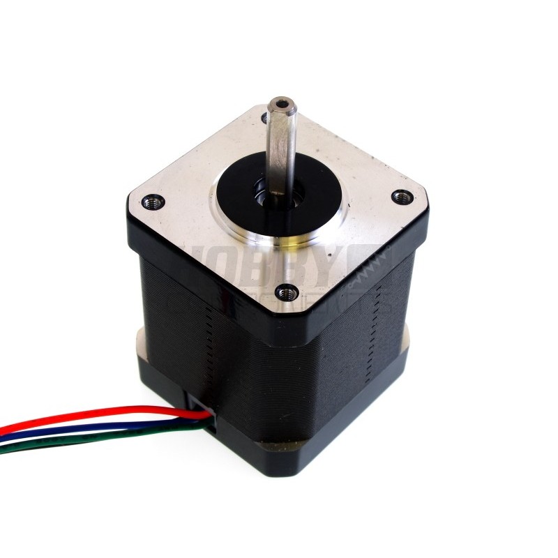
Motor
Unipolar stepper motor
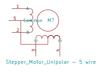
Figure 1. Unipolar Stepper Motors Coils
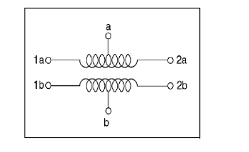
Bipolar Stepper Motor
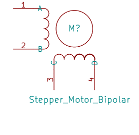
Figure 2. Bipolar Stepper Motor Coils
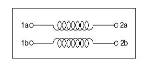
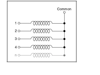
Figure 3. Hybrid Stepper Motor Coils
Step Angle
Driving Unipolar Stepper Motors
Full Step
Table 1. One Phase on Sequence

Figure 4. One Phase Steps
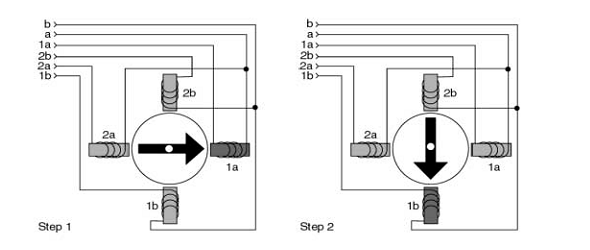

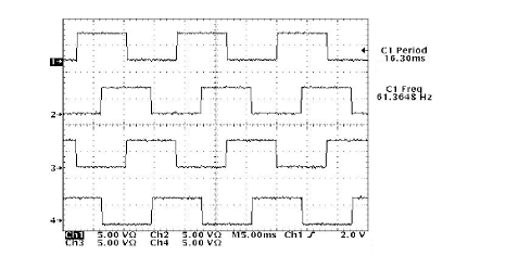
Figure 5. One Phase on Steps Sequence
Two Phases on Mode (Alternate Full step Mode)
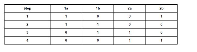
Figure 6. Two Phases on Steps
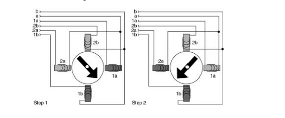

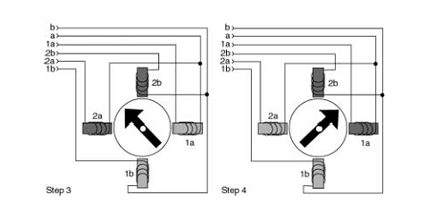
Figure 7. Two Phases on Steps Sequence
Half Step Mode Table 3. Half Step Sequence
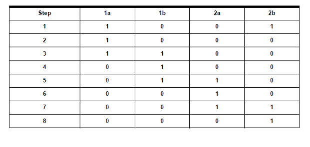
Figure 8. Half Step Sequence
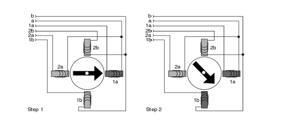

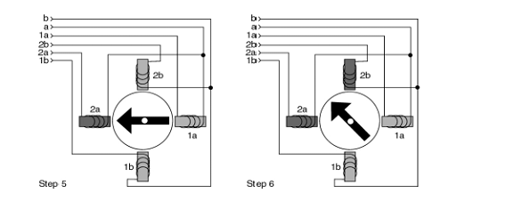
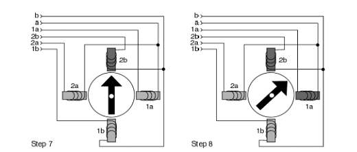
Figure 9. Half Step Sequence
Micro step
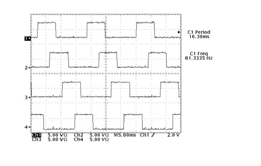
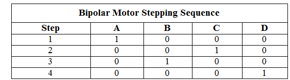
Driving Bipolar Stepper Motors
Advantages
Applications
/*  Name     : UARTmain.c
 *  Purpose  : Source code for Unipolar full step stepper motor interface with ATMEGA16.
 *  Author   : Gemicates
 *  Date     : 2017-09-09
 *  Website  : www.gemicates.org
 *  Revision : None
 */


#define F_CPU 8000000UL			// Define CPU Frequency e.g. here its 8MHz
#include <avr/io.h>		        // Include AVR std. library file
#include <util/delay.h>		        // Include delay header file
#define lcd_clrscr()
	#define lcd_puts()

int main(void)
{
	int period;
	DDRD = 0x0F;			// Make PORTD lower pins as output
	PORTD=0x00;
	period = 100;
   				        // Set period in between two steps of Stepper Motor

	while (1)                       // Rotate Stepper Motor Anticlockwise with Full step sequence; Full step angle 90 degree

	{

PORTD = 0x09;
_delay_ms(period);
PORTD = 0x0C;
_delay_ms(period);
PORTD = 0x06;
_delay_ms(period);
PORTD = 0x03;
_delay_ms(period);
}
}
/*  Name     : main.c
 *  Purpose  : Source code for Unipolar half step stepper Motor interface with ATMEGA16.
 *  Author   : Gemicates
 *  Date     : 2017-09-11
 *  Website  : www.gemicates.org
 *  Revision : None
 */


#define F_CPU 8000000UL		  // Define CPU Frequency e.g. here its 8MHz
#include <avr/io.h>	          // Include AVR std. library file
#include <util/delay.h>		  // Include delay header file
#define lcd_clrscr()
	#define lcd_puts()

int main(void)
{
	int period;
	DDRD = 0x0F;	          // Make PORTD lower pins as output
	PORTD=0x00;
	period = 100;
   				  // Set period in between two steps of Stepper Motor

	while (1)
	{

	                          // Rotate Stepper Motor clockwise with Half step sequence; Half step angle 45 degree


			PORTD = 0x09;
			_delay_ms(period);
			PORTD = 0x08;
			_delay_ms(period);
			PORTD = 0x0C;
			_delay_ms(period);
			PORTD = 0x04;
			_delay_ms(period);
			PORTD = 0x06;
			_delay_ms(period);
			PORTD = 0x02;
			_delay_ms(period);
			PORTD = 0x03;
			_delay_ms(period);
			PORTD = 0x01;
			_delay_ms(period);
			}

}
/*  Name     : main.c
 *  Purpose  : Source code for Unipolar wave drive stepper motor interface with ATMEGA16.
 *  Author   : Gemicates
 *  Date     : 2017-09-10
 *  Website  : www.gemicates.org
 *  Revision : None
 */

#define F_CPU 8000000UL			// Define CPU Frequency e.g. here its 8MHz
#include <avr/io.h>		        // Include AVR std. library file
#include <util/delay.h>		        // Include delay header file
#define lcd_clrscr()
	#define lcd_puts()

int main(void)
{
	int period;
	DDRD = 0x0F;		        // Make PORTD lower pins as output
	PORTD=0x00;
	period = 100;
   				        // Set period in between two steps of Stepper Motor

	while (1)
	{


PORTD = 0x08;
_delay_ms(period);
PORTD = 0x04;
_delay_ms(period);
PORTD = 0x02;
_delay_ms(period);
PORTD = 0x01;
_delay_ms(period);
}
}
/*  Name     : main.c
 *  Purpose  : Source code for Bipolar stepper motor interface with ATMEGA16.
 *  Author   : Gemicates
 *  Date     : 2017-09-11
 *  Website  : www.gemicates.org
 *  Revision : None
 */

#define F_CPU 8000000UL			// Define CPU Frequency e.g. here its 8MHz
#include <avr/io.h>			// Include AVR std. library file
#include <util/delay.h>		        // Include delay header file
int main(void)
{
	int period;
	DDRD = 0x0F;			// Make PORTD lower pins as output
	PORTD=0x00;
	period = 100;
   				        // Set period in between two steps of Stepper Motor


	while (1)
	{


PORTD = 0x01;
_delay_ms(period);
PORTD = 0x04;
_delay_ms(period);
PORTD = 0x02;
_delay_ms(period);
PORTD = 0x08;
_delay_ms(period);
}
}